
By Roy Goodrum
Removal
1. Remove speedometer drive cable from gearbox.
2. Remove four securing screw holding instrument to panel and extract gauge.
3. Unscrew the three screws just behind bezel and slide bezel forward out off housing.
4. Unscrew three retaining screws on rear surface of housing and remove movement.
5. Take care at this stage as it is likely that some of the small (1/16″ Dia.) ball bearings will be loose in the housing, or held loosely on the movement by grease.
6. Carefully lever the indicator hand away from the central pin and unscrew the three small screws holding the dial in position..

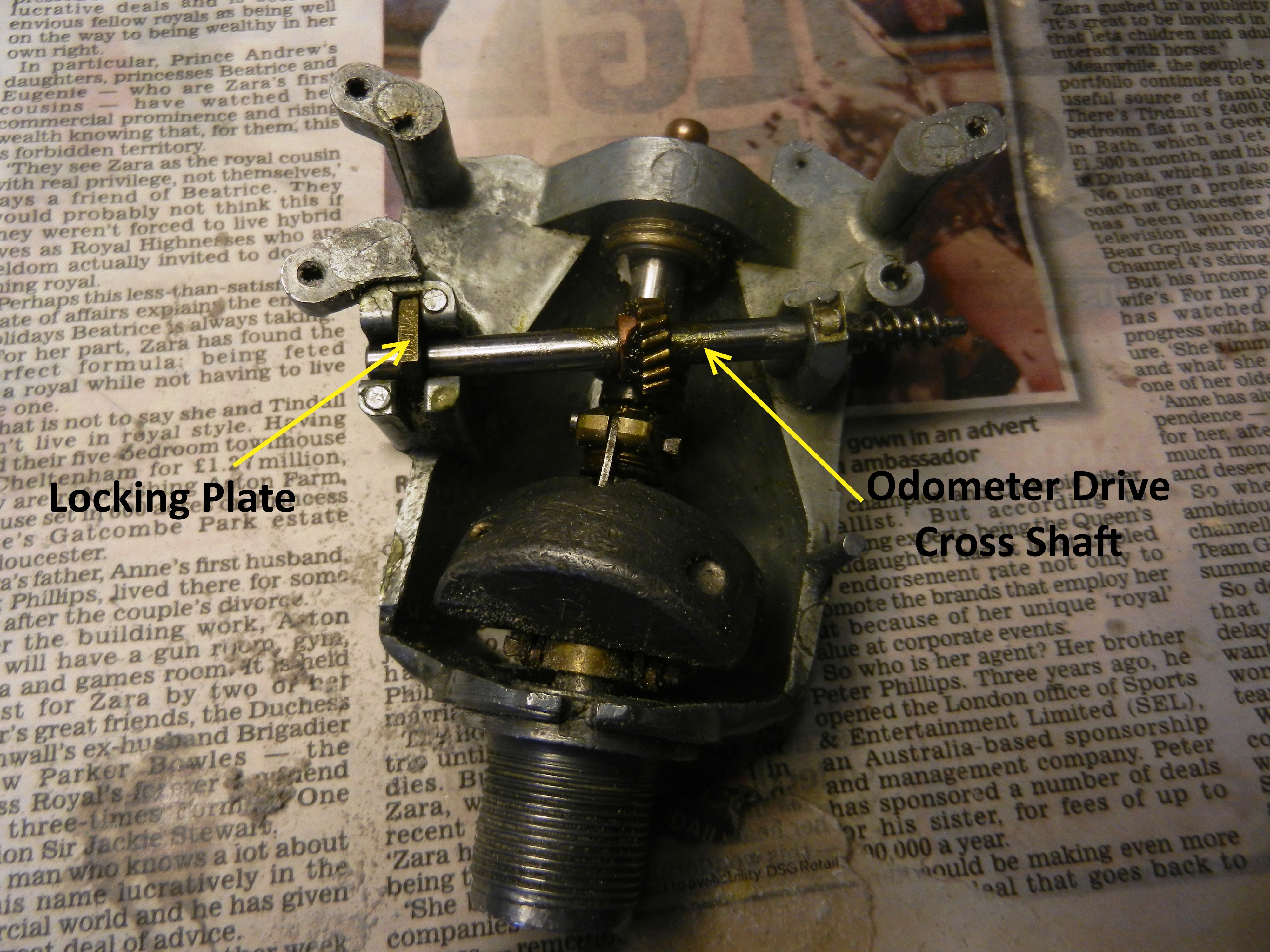
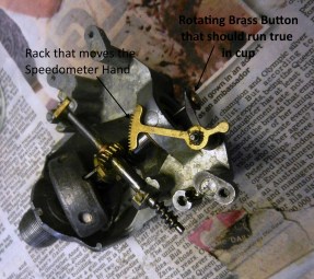
7. Unscrew the backing plate containing the odometer dials. This releases the lever arm that moves the speedo hand.

8. Unhook the arm from the central pin head and place aside.
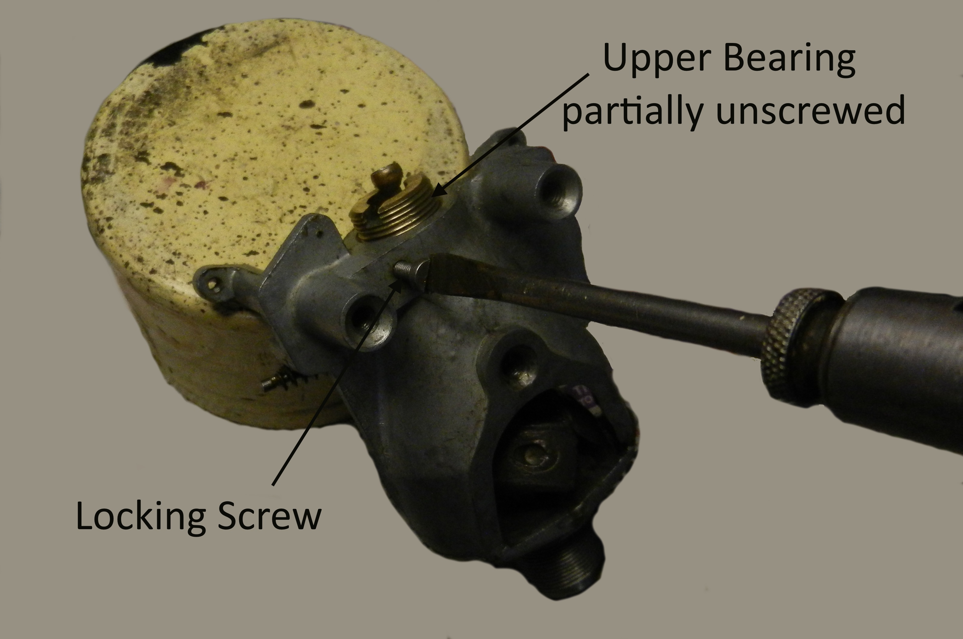
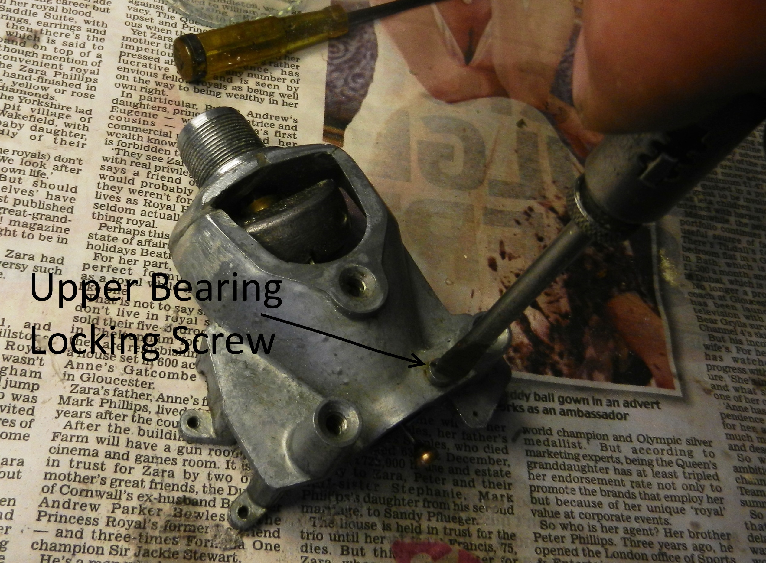
9.. Remove the small brass locking key and remove the cross shaft.
10. Release the upper bearing locking screw that can be found to the side of the bearing.
11. The upper bearing can now be unscrewed. Again care to be taken that no balls are lost, they are very difficult to find if inadvertently dropped
12. The Centrifuge shaft assembly can now be lifted out. Again take care that the ball bearings from the lower bearing are not lost.
13. Inspect and determine the cause of malfunction and make the required corrections.
Reassembly
1. The lower bearing was checked and the 15 ball bearings held in place with grease. Then the four missing balls were fitted into the upper bearing track, both bearings then having 15 balls each the balls in the upper bearing were also secured in place with grease. The bearing was then carefully inverted and slid over the shaft taking care not to dislodge any of the balls in the process.
2. With the upper bearing screwed into place to give minimal end float, but free rotation, the locking screw is tightened to resist inadvertent movement during service
3. Fit casting into speedo housing, the lower portion is a very close fit so has to be carefully fitted ensuring that the three securing screws seat correctly into position without undue strain being placed on the repaired casting.
4. Install odometer cross shaft in position, locking in place with the brass key plate
 .
.
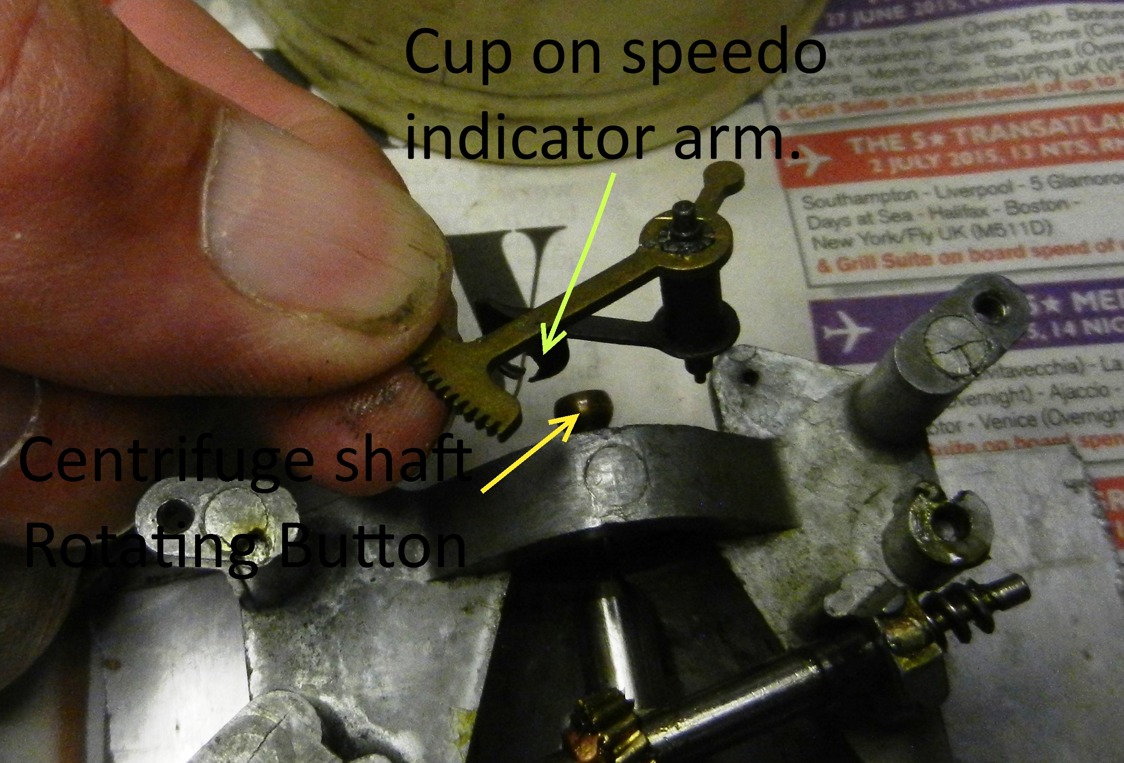
5. Install speedo arm ensuring that there is a little tension on the dial indicator hand “Hair-Spring” giving just enough pressure to seat the cup to its seating.
6. At this stage it is convenient to return the odometer readings to Zero mileage, or to any other mileage that may be desired.

7. Refit dial – The exchange unit fitted to ‘Jane’ had a paper facing giving an excellent appearance. If the dial of the subject speedo has become faded, and it is desired it may easily be renewed at this stage.
8. At this point check the run-out of the brass button in the speedo arm cup. Any run-out will give fluctuations on the hand whilst registering vehicle speed.
9. Replace movement in casing and tighten the three screws in back.
10. Replace chrome bezel and secure with the three screws in edge of casing.
11. Refit speedo cable taking note that the smaller square drive is engaged in speedo. Then refit to vehicle and the job is complete.


You must be logged in to post a comment.